

One-Way Clutch History and Metal Fatigue


Early inventors realized the advantage of using a rack-an-pinion mechanism instead of a crank-arm to convert a piston's reciprocating motion to rotating motion of a drive shaft. The method is inherently more mechanically efficient. The heart of a rack-and-pinion power linkage is a one-way clutch. These clutches are also variously known as freewheel clutches, overriding clutches, one-way bearings or mechanical diodes. The clutch locks and transfers torque to the drive shaft during the piston's power stroke and then unlocks and "freewheels" during the piston's return stroke.
- 1Early Rack and Pinion Engines
Early Rack-and-Pinion Drive Engines
The Barsanti-Matteucci Engine
The Barsanti-Matteucci engine is often credited as the first internal combustion engine.[1] A so-called "atmospheric engine," it was the first internal combustion engine design to acheive commercial success.[2] The engine used a simple pawl and ratchet mechanism for its one-way clutch.
The Otto-Langen Engine
Famous inventors Nicholas Otto and Eugen Langen improved on the Barsanti-Matteucci design to produce the "Otto-Langen free-piston" engine. This rack-and-pinion drive engine "... Carried all before it and held command of the market for many years, during which time a large number were built."[2] The engine's success was due to its much greater fuel efficiency over its main competitor, the famous Lenoir engine. The engine acheived 11% to 12% thermal efficiency (truely remarkable for that early era!) and several thousand engines were manufactured. [3] [4]
Eugen Langen devised a revolutionary and ingenious device to replace the primitive pawl and ratchet clutch of the Barsanti-Matteucci engine. Langen's "overriding" clutch was the world's first roller-ramp freewheeling clutch. His basic design is used in today's roller-ramps clutches, which are found in widespread uses everywhere.
Nicholas Otto went on to invent the famous four-stroke engine which is named after Otto (the Otto-cycle), and which replaced his rack-and-pinion drive with a crank-arm. The crank-arm system is less efficient, but it could produce more power and handle higher engine RPM.
Current Clutch Technology
An internal combustion engine using a rack-and-pinion drive could be built with currently available clutches, but the clutches would fail after a few hours operation due to metal fatigue.Why Metal Fatigue Affects Today's Clutch Technology
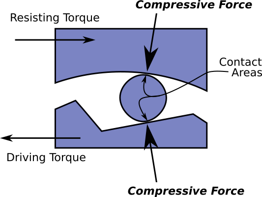
Current clutch technologies suffer metal fatigue because tiny contact surfaces have to endure tremendous compressive force during torque tranmission. This produces tremendous pressure at the contact surfaces. The following chart graphs the number of stress-relief cycles (N) against stress pressure (S) for steel and aluminum. The chart shows that aluminum will eventually crack, even at low pressures, if subject to a great enough number of cycles. Most materials show this behavior. But steel is an amazingly strong material showing a remarkable characteristic: as long as the stress pressure is kept below a certain level it will never show fatigue cracks. This pressure level is marked "endurance limit" on the chart, meaning steel's endurance is UNLIMITED below this pressure. The problem with current clutch technologies is that contact stress rises far beyond the endurance limit. [5]
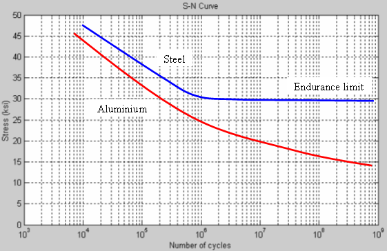
Cycle Lifetime (N) vs Stress (S) for Steel and Aluminum
Roller-Ramp and Sprag Clutches
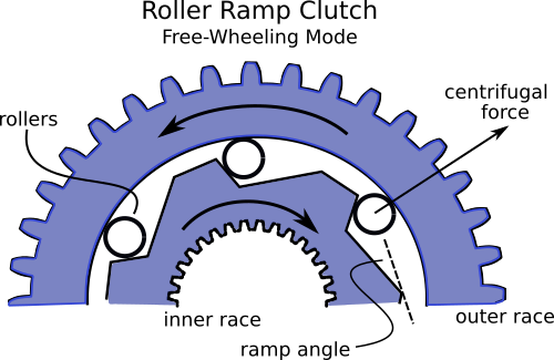
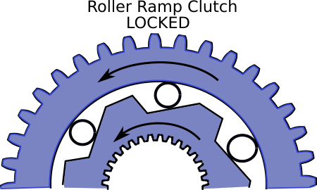
A roller-ramp clutch locks in order to transfer torque between two rotating "races". The clutch locks when the rollers jam between a ramp surface on one race and the circular contact surface on the second race. For friction to hold tight during lock the angle of the ramp has to be relatively shallow. If the ramp is too steep the rollers will merely slip and no lock is achieved. When torque is reversed the rollers release and spin freely as the races counter-rotate (freewheeling mode).
The smaller the ramp angle the greater the compressive force squeezing the rollers during locked operation. A hundred pounds of torque acting on a roller can produce a thousand pounds or more of compressive force. But this tremendous force is focused on the miniscule contact areas where the rollers and races touch, causing astronomical pressures. The same friction physics produce the same pressures at the contacts in sprag clutches.
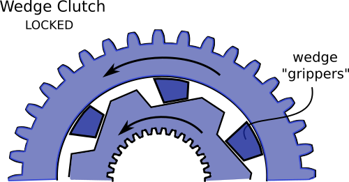
The "Wedge" Clutch
Numerous attempts have been made to solve the metal fatigue problem, described above, by replacing the rollers and sprags in one-way clutches with wedge-shaped clutch elements. If a wedge is placed between the ramp and counter-race surface the tiny line-contacts of the rollers are replaced with large area contact surfaces. Enlarging the contact areas could easily bring pressures below the endurance limit for steel, eliminating metal fatigue. This appears to be an ideal solution. But several problems have hampered development of workable wedge clutch technology.
Making the Wedges Lock
Unlike the case with rollers and sprags, it is not easy to make wedges lock the rotation of the clutch's two races. Instead of locking, the wedge clutch races may fall into a constant slipping rotation. Slippage produces friction and heat, while transferring very little torque. To attain locking, wedge clutches must place the ramps on the inner race, and ramp angles must be shallow.Jamming
Because of the shallow ramp angle needed to produce locking action in a wedge clutch, the wedges are vulnerable to jamming. If a wedge jams the clutch will not release when freewheeling should commence. Significant force must be applied to free up a jammed wedge clutch. A clutch must be guaranteed against jamming for use in a rack-and-pinion engine.
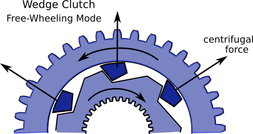
Freewheeling Friction
The clutch in a rack-and-pinion drive engine must generate very little friction during the freewheel portion of the piston's motion. But wedge clutches inherently produce high levels of freewheeling friction. As evindent in the illustration at right, centrifugal force press the wedges against the outer race surface during freewheeling. During high speed counter-rotations this force is substantial, creating high levels of friction and surface wear.
One may quickly observe that reversing the design and placing the ramps on the outer race will both eliminate freewheel friction and the jamming problem in wedge clutch. Unfortunately, wedges do not lock in this configuration.
| [1] Wikipedia: "Barsanti-Matteucii engine" | [4] Missiseipi.com: "Otto Langen atmospheric engine" | |
| [2] Innoble Technologies: "Internal Combustion engine" | [5] Wikipedia: "S-N Curves" | |
| [3] Desta Lemma (BSc, MSc), ADDIS ABABA UNIVERSITY, MECHANICAL ENGINEERING DEPARTMENT "Internal Combustion Engines" (pdf) |