


The J-Clutch
The J-Clutch is purpose designed for rack-and-pinion based internal combustion engines. The design eliminates metal fatigue and also includes other crucial features. On November 7, 2017 the U.S. Patent Office granted all eleven patent claims applied for on the J-Clutch.[1] Additional J-Drive engine innovations and international patent claims are pending.
Current Clutch Technology
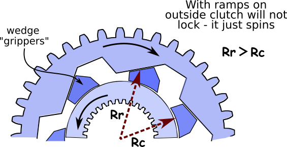
"Wedge Clutch" Failures
An Exclusive Automotive Focus
Most all efforts at improving the freewheeling clutch focus on the clutch component in vehicle automatic transmissions. Given the monetary potential of inventions that benefit the automotive industry this exclusive focus on the automotive clutch is understandable.
The 2-Dimensional Limitation
Great cost benefits are attained in the manufacture of an automotive one-way clutch by making the clutch as thin as possible. Conversely, a thicker clutch has a serious cost disadvantaged. For this reason, among others, current one-way clutch designs are exclusively 2-dimensional. Specifically, the forces and physics operating within the clutch operate on a flat plane. These forces are easily visualized and diagrammable on a flat sheet of paper.
New Wedge Clutch Designs
This decade several patents have been awarded for new "wedge clutch" designs. The components of these clutches are generally fabricated out of stamped metal plates, resulting in a very thin profile. As observed above, a thin clutch is advantageous for the manufacture of automatic transmissions. But wedge clutches have flaws that make the design unworkable for the rack-and-pinion drive engine. More about the wedge clutch here.
A 3-D Solution
The J-Clutch Load Rotor
In the J-Clutch design the terms "inner race" and "outer race" are obsoleted. (All conventional clutches today are built of an inner and outer race.) At the heart of the J-Clutch is its "load rotor." The load rotor has two beveled contact surfaces which may be called "races." The load rotor races are seperated by a generous gap (see illustration at right). A narrow inner shaft connects the two discs on which the races reside. Splines provide for connection to the engine's drive shaft.
The J-Clutch Driving Gear
The J-Clutch driving gear comprises the pinion part of the engine's rack-and-pinion drive linkage, and provides ramp surfaces for engaging the clutch's "gripper" elements. The driving gear is situated between the load rotor's two discs. The curvature of the ramp surfaces is specially formulated to maintain alignment of the J-Clutch grippers, distribute pressures evenly across the contact sufaces, and to allow significant surface wear.
The J-Clutch Grippers
The J-Clutch grippers provide three contacting surfaces: a gripping surfaces at each end and a slipping surface in the middle. When in locked position the grippers press against the load rotor races and the driving gear ramps. The grippers provide large area contact surfaces that eliminate metal fatigue. Low-friction pads or coatings may optionally be deployed on gripper or ramp surfaces in some models. This technique helps minaturize the clutch for use in small, low power engines.

Working Principles
The 3-D geometry of the J-Clutch guarantees locking action of the new wedge grippers. Lock is achieved at a high ramp angle due, in part, to the beveled angle of the load rotor contact surfaces. Inward facing ramps mean that the grippers fully disengage from the load rotor races during freewheeling, eliminating freewheeling friction. The formula specifying the ramp curvature allows for substantial surface wear during the life of the clutch, with no effect on performance. Comprehensive technical details are provided in U.S. Pat 9,810,272.[1]


Coordinates and Terms used in Designing the J-Clutch
Most images on this web page are from the J-Clutch patent: U.S. Pat 9,810,272.[1]
| [1] Alan K. Johnson DBA Friction Physics: The J-Clutch Patent U.S. Pat 9,810,272 (pdf) | ||